Project Description

RM AFH Series 1000 / 2000 / 3000
C2 TELEMETRY AND CONTROL DATA LINKS
|
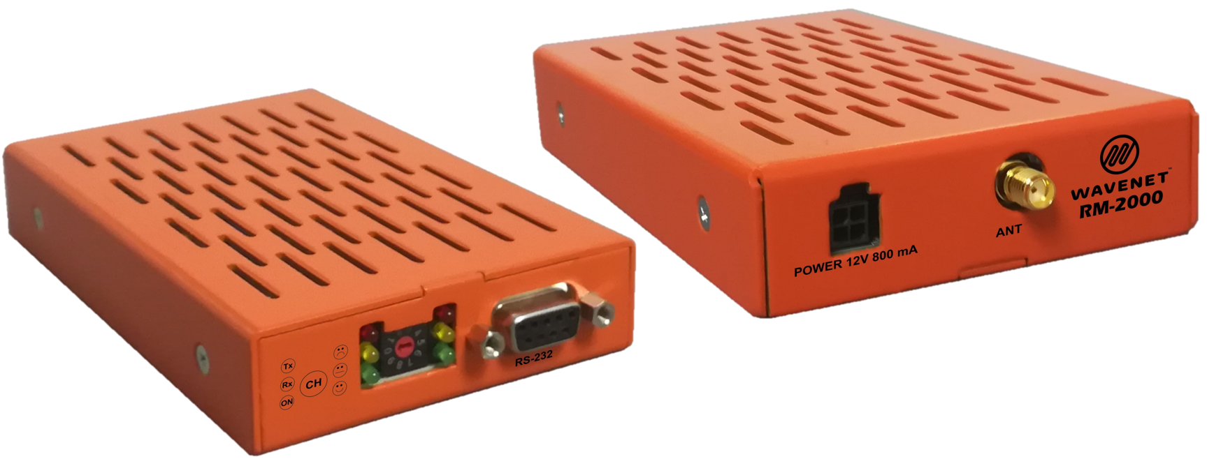
RM-1000/2000/3000 RADIO MODEM series allows bidirectional transparent data communication, at 80.000 bps (uplink + down link) maximum speed. Therefore this device is developed to make a bidirectional point-to-point communication, but it can be manufactured to make a one way broadcast communication point-to-multipoint. It is specially designed to reach distances from 40-50 km to 300 km, depending of version 1000, 2000 or 3000. The equipment has an internal error detection mechanism using CRC 16, in order to send only the valid data to RS 232 serial port 1. It also incorporates a HW flow control system (RS 232 serial port configuration) using RTS and CTS lines to avoid data storage memory overflow. Since RM Series work like a DCE communication equipment, it is mandatory to take into account the pin out for this kind of systems. A female DB 9 connector allows the RM Series devices connect to a data terminal. It also has a female SMA for antenna connection, the power supply connector and a channel selector to choose the channel of 10 choices. There are also two led indicator lines to show, on one hand, power on, Tx and Rx, and on the other hand the RSSI level. This RADIO MODEM is able to adapt its communications capacity in noisy or interfered environment, using a new method called Adaptive Frequency Hopping. This way, the RADIO MODEM, automatically, uses a combination of frequencies with a certain pattern. The system continuously analyzes each cannel of the pattern, adapting automatically to the interference or interferences detected in that channels. The manual channel selector (0 to 9) allows to select 10 different patterns. One of the devices, air side or ground side, is factory set as “Master”, and the other device as “Slave”. “Master” device controls the patterns, adaptations and everything referred to media Access and communications for synchronism. We usually set the ground side device as “Master”, and the air side device as “Slave”. We can change this configuration in factory under demand. |

